
When I volunteer as a programming mentor at CoderDojoTC we are in a large room with about 70 people. Some of the tables are setup for students learning to program Arduinos. When students first arrive in the room it is nice to have a sign directing them to the right tables. Since I know that color and motion are great ways to get kid's attention I decided to create a colorful programmable sign using addressable LED strings.
Since I made the sign I have had multiple requests from teachers and other Arduino mentors for instructions on how to make their own sign. These signs are ideal for display cases of a the science area of a school or a STEM program. So here are the detailed instructions on making your own sign.
Design goals
I had three design goals for this sign:- Use standard components that are easy for teachers and students to program with any moving color patterns that they want
- Make it low cost (under $20)
- Make it simple to construct - it should take about an hour once you have all the parts
Parts
Here are the parts I used:- 50 pixel LED string ($12) sample on ebay
- Scrap Plexiglas - 20"X 5" and 1/4 inch thick
- Arduino Nano ($3) sample on ebay
- USB cable ($2) sample on ebay
- 1/2 size 400 connector solderless breadboard ($1.50)
- Two momentary push buttons (10 cents each) sample on ebay
- A few short 22-gauge wires
- USB charger ($1.10) sample on ebay
- Scrap wood stand (3" X 8" X 3/4 inch think)
- 3x 1 inch wood screws
Here are the steps to make your own sign.
Step 1: Calculate the size of sign and spacing of the pixels
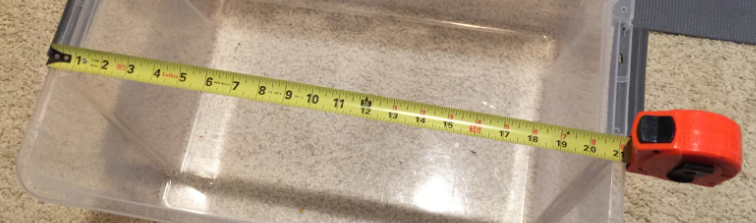
When we do our CoderDojo sessions or when I do maker fairs I take along a plastic bins that are about 20 inches across. I designed the sign to fit in the box, so I made the width 19 inches. To keep the sign proportional to the word "ARDUINO" I needed a sign that was about five inches high.
I wanted to use a 50 pixel LED string so I calculated that most of the letters (except the letter "I") needed to be 7 or 8 pixels each. The I only needed 4 pixels fir the letter "I". So 50 pixels would be fine. You can use longer chains of LEDs if you need to by connecting the DATA OUT to the next string's DATA IN.
Step 2: Find some scrap diffused white Plexiglas
I went to a local surplus store (The AxMan) near my home and found a large piece of 1/4 inch think Plexiglas for $8. I could easily make six signs out of this one piece. You want the translucent kind since it is ideal for diffusing the light.
Step 3: Cut and Sand the Plexiglas
I cut the Plexiglas on a jig saw and sanded one side with 100 grit sandpaper. I needed to take the gloss out of the Plexiglas so the hot glue would stick to the surface. The front side of the sign can glossy, just the back side needs to be roughened up.Step 4: Print the "ARDUINO" sign letters on paper

I used PowerPoint to lay out a two-page sign. I used white letters on a black background and printed it on standard photocopy paper on two pages. A template in PowerPoint of the sign is here:
https://github.com/dmccreary/moving-rainbow/tree/master/src/displays/signs/Arduino-19-inch-template.pptx?raw=true
Make sure you don't print on thick paper, it will block out too much of the light.
Make sure you don't print on thick paper, it will block out too much of the light.
Step 5: Tape letters to the sign and locate LED positions

I then taped the letters to the front of the sign and then turned the sign over. I located each letter and put small marks where each LED would be positioned over the white letters.
Step 6: Hot glue LEDs in place

This was the hardest part of the project. This is also where a little planning and patience pays off. I had to glue the tip of each pixel down onto the Plexiglas so it would stand up. I had to wait until the hot glue hardened before I could go on to the next pixel. I also had to make sure that the last pixel in each letter was near the start of the next letter. My string only had three inches between each pixel so I had to be careful about the order of pixels in each letter.
If you need more than three inches you may need to cut the wires and solder in some extension wire. Just make sure to keep the colors matching. I also left 3/4 inch of room at the bottom so I had room to mount the sign on the wooden stand.
Step 7: Attach the stand to the Plexiglas

Once the LEDs were hot glued onto the Plexiglass I attached the wooden stand to the Plexiglas using three wood screws. I pre-drilled holes so that they were easy to screw in.
Step 8: Mount the breadboard with Arduino to the stand

Most of the 1/2 size breadboards come with an adhesive backing. I just peeled off the backing and put it directly on the top of the stand. The circuit on the breadboard is pretty simple. The power and ground of the LED strip must be connected to the 5V and GND of the Arduino Nano and the momentary buttons need to pull pins 2 and 3 to ground when they are closed. One button can be used to go to the next pattern and one goes to the previous patterns. Note that I put a drop of hot glue over the connectors to the LED strip. I also soldered solid wire to the ends of the LED wires. Note that in the version I purchased the white is ground, the red is 5v and the green is the DATA IN. Make sure you use the correct end of the strip (not the DATA OUT).
Here is the circuit I used:

Note that the buttons are hooked to pins 2 and 3 of the Arduino Nano. These are the interrupt pins. The pins are configured as INPUT_PULLUP so they pull the pins up to 5v when the buttons are OPEN. Pressing the buttons down pulls the pins voltage down to ground and moves the pattern mode to the next or previous pattern. Note that you don't need any pullup resistors when you use these settings.
Step 9: Load the software on the Arduino
I then plugged in the USB cable and downloaded some sample code to make the LEDs display a nice pattern. Many of these sample programs are on the Moving Rainbow github site here:
https://github.com/dmccreary/moving-rainbow
The github has many programs and a git-generated book here:
http://moving-rainbow.readthedocs.io/en/latest/README/
The github has many programs and a git-generated book here:
http://moving-rainbow.readthedocs.io/en/latest/README/
You can find the program that allows you to switch between modes here:
https://github.com/dmccreary/moving-rainbow/blob/master/src/mini-maker-faire/led-strip-two-buttons/led-strip-two-buttons.ino
Note that this sample program uses the Adafruit Neopixel library. You can use the Sketch -> Include Library...Manage Libraries... function and just search for "Neopixel" to include the library. There are complete instructions in the online Arduino Moving Rainbow book.
There are about a dozen color patterns that you can choose. We encourage you to have your students write their own patterns, each within its own subroutine.
Step 10: Add a wall adapter

Here is a video of one of the patterns:
There are a few other ideas:
- Create a version of the software that continually cycles through each of the modes.
- Hook up a Passive Infrared (PIR) motion sensor to automatically change the mode when there is motion but go into a low-power mode when there is no motion detected.
- Have students each add their own pattern and alternate between these patterns